Arduino Hall Effect Sensor Circuit

Interfacing Hall Effect Sensor With Arduino Arduino Hall Effect Sensor

Noted Hall Effect Sensor Arduino Program Hall Effect Arduino Sensor

Building Gizmos With Arduino Latching Hall Effect Sensor Hall Effect Arduino Arduino Sensors

Hall Effect Sensor Circuit In 2020 Hall Effect Sensor Circuit

How To Use A Hall Effect Sensor With Arduino Education Maker Pro Hall Effect Arduino Sensor

Ac Current Measurement Using Arduino And Hall Effect Sensor Acs712 Arduino Hall Effect Sensor

Whenever it will be placed in the region of magnetic field then it will detect it and will give us the output.
Arduino hall effect sensor circuit. We will then connect this ic to an arduino so that we the arduino can read the voltage output by the a1302 and we can display the readings to the computer screen. Hall effect sensor with arduino circuit and code hall effect sensor module interfacing with arduino this module is used to detect the presence of magnetic. If you remember the arduino waterflow sensor tutorial we implemented earlier the main component of the water flow sensor is the hall effect ic. Acs acs arduino arduino projects current sensor arduino interfacing current transducer symbol hall effect current sensor circuit hall effect sensor mains current sensor share on tumblr monitoring the current flow in a device.
A hall effect sensor can be used in most places where you would use an ultrasonic proximity detector or an infrared sensor to detect changes or movement in the environment. The vcc of the sensor is connected to arduino s 5v power pin. The only primary difference is that a hall effect sensor requires a magnet to also be employed for it to detect changes while ir and ultrasonic sensors are able to function. Furthermore a 10k resistor is connected.
The gnd of the sensor is connected to the gnd pin on the arduino. That is the anode connected to the hall effect sensor and the cathode with the black line on the arduino side. Interfacing arduino and acs712 hookup. We have one input which is the sensor and one output which is a led.
Here two hall effect sensors pinout given the a1321 range sensor gives analog out linear sensor and us1881 range sensor gives digital out both sensors can be easily interfaced with arduino board if we use digital hall effect sensor we need to give bias from 5v to the output terminal through 10kω resistor. Acs712 can measure current precisely and accurately if properly managed. A hall effect sensor works on the principle of well hall effect. This is an typical application circuit from datasheet.
Simply speaking a hall effect sensor or ic detects motion position or change in magnetic field strength of either a permanent magnet an electromagnet or any. The vout or signal pin of the hall effect sensor is connected to the arduino s interrupt pin digital pin 2. I have gone through various blogs on internet about interfacing acs712 current sensor with arduino and other microcontrollers. The hall effect sensor we will use in this circuit is an a1302 hall effect sensor manufactured by allegro.
As per the breakout application note hall effect current sensor connected with target load and output signal is connected with well known arduino s a0 analog input pin 0. This ic can detect magnetic fields. Interfacing the hall effect sensor with arduino is really simple. In this tutorial i am going to measure dc current using acs712 hall effect based linear current sensor and arduino uno.
Hall effect sensor arduino code.

Hall Effect Sensor Circuit Schematic Hall Effect Sensor Humidity Sensor

Hall Effect Sensor With Arduino Circuit And Code Arduino Projects Arduino Wifi Arduino

Noted Hall Effect Current Sensor Circuit Hall Effect Sensor Arduino

A3144 Hall Effect Sensor Pinout Working Alternatives Datasheet Hall Effect Sensor Electronic Circuit Design

Hall Effect Sensor To Sense Magnetic Proximity Arduino Hall Effect Circuit Diagram

Hall Effect Sensor Pinout Hall Effect Sensor Arduino

Interfacing Acs712 Current Sensor With Arduino Measure Current With Arduino Measuring Current With Arduino Arduino Sensor Arduino Circuit

Ac Current Measurement Using Acs712 Hall Effect Current Sensor And Arduino Arduino Hall Effect Arduino Projects

Fan Rpm With Internal Hall Effect Sensor And Arduino Intro To Hardware Interrupt And Lcd Display Hall Effect Arduino Sensor

How To Use Hall Effect Sensor With Arduino Working Hook Up Guide And Relay Control In 2020 Hall Effect Arduino Sensor

Nrf24l01 Basic Control Led Arduino Elec Cafe Com Arduino Projects Arduino Wifi Arduino

How To Build A Hall Effect Sensor Circuit Hall Effect Sensor Hall

Fan Rpm With Internal Hall Effect Sensor And Arduino Intro To Hardware Interrupt And Lcd Display

How To Measure Ac Current Using Hall Effect Sensor With Arduino Or Other Common Microcontrollers Hall Effect Arduino Sensor

Pin By Marino Alberto On I N T E R N E T C Wi Fi Usb Redes Arduino Electronics Projects Arduino Projects

How To Measure Ac Current Using Hall Effect Sensor With Arduino Or Other Common Microcontrollers With Images Hall Effect Arduino Arduino Projects

Water Flow Sensor Arduino Circuit Arduino Arduino Circuit Arduino Projects

Arduino Rpm Hall Effect Arduino Arduino Projects Hall Effect
Https Encrypted Tbn0 Gstatic Com Images Q Tbn 3aand9gcrajt S9bgw76irubyzfxspg9wy6ma Afrotdh35fhq0fpv3clf Usqp Cau

Inductive And Hall Effect Rpm Sensors Explained Kiril Mucevski Linkedin Hall Effect Sensor Automotive Electrical

Simplified Arduino Ac Current Measurement Using Acs712 Hall Effect Sensor Arduino Hall Effect Sensor

Water Flow Sensor Measure On Display On 16x2 Lcd Hackster Io Electronic Circuit Projects Sensor Arduino
How To Use Hall Effect Sensor With Arduino Hall Effect Arduino Projects

How To Use Hall Effect Sensor With Arduino Working Hook Up Guide And Relay Control

A3144 Hall Effect Sensor Pinout Hall Effect Electronic Circuit Projects Sensor

A Slightly More Expensive Gaussmeter Diy Electronics Hall Effect Electronics Projects

How To Use Hall Effect Sensor With Arduino Working Hook Up Guide And Relay Control In 2020 Hall Effect Arduino Sensor

Oh137 Arduino Hall Switch Tutorial Arduino Arduino Sensors Electronics Circuit

Introduction Hall Effect Switches Sensors Circuits Tutorial Hall Effect Circuit Sensor

Hall Effect Sensor As Limit Home Switches Arduino Programming Arduino Programming Arduino Hall Effect

Arduino Magnetometer Arduino Projects Arduino Useful Arduino Projects

Project Shows How To Control Sensored Brushless Dc Bldc Motor With Arduino Uno Sensored Bldc Motor Uses Hall Effect In 2020 Arduino Arduino Projects Arduino Circuit

How To Use Hall Sensor With Avr Microcontroller Atmega16 Microcontrollers Circuit Diagram Electronics Circuit

Arduino A3144 Hall Effect Sensor Code Generator In 2020 Hall Effect Coding Arduino

Circuit Diagram For Magnetic Field Measurement Using Arduino Arduino Magnetic Field Arduino Projects

Simplified Arduino Ac Current Measurement Using Acs712 Hall Effect Sensor Arduino Hall Effect Electronics Projects

Arduino Tutorial Hall Effect Sensor From Banggood Com And Arduino Uno Youtube Hall Effect Arduino Arduino Sensors


Sensored Brushless Dc Bldc Motor Control With Pic16f877a In 2020 Arduino Simple Circuit Arduino Controller

Use A Hall Effect Sensor To Detect The Presence Of A Magnet And Make A Speedometer A Burglar Alarm And More Hall Effect Arduino Sensor

Arduino Based Magnetic Field Measurement Arduino Electronics Projects Microcontrollers
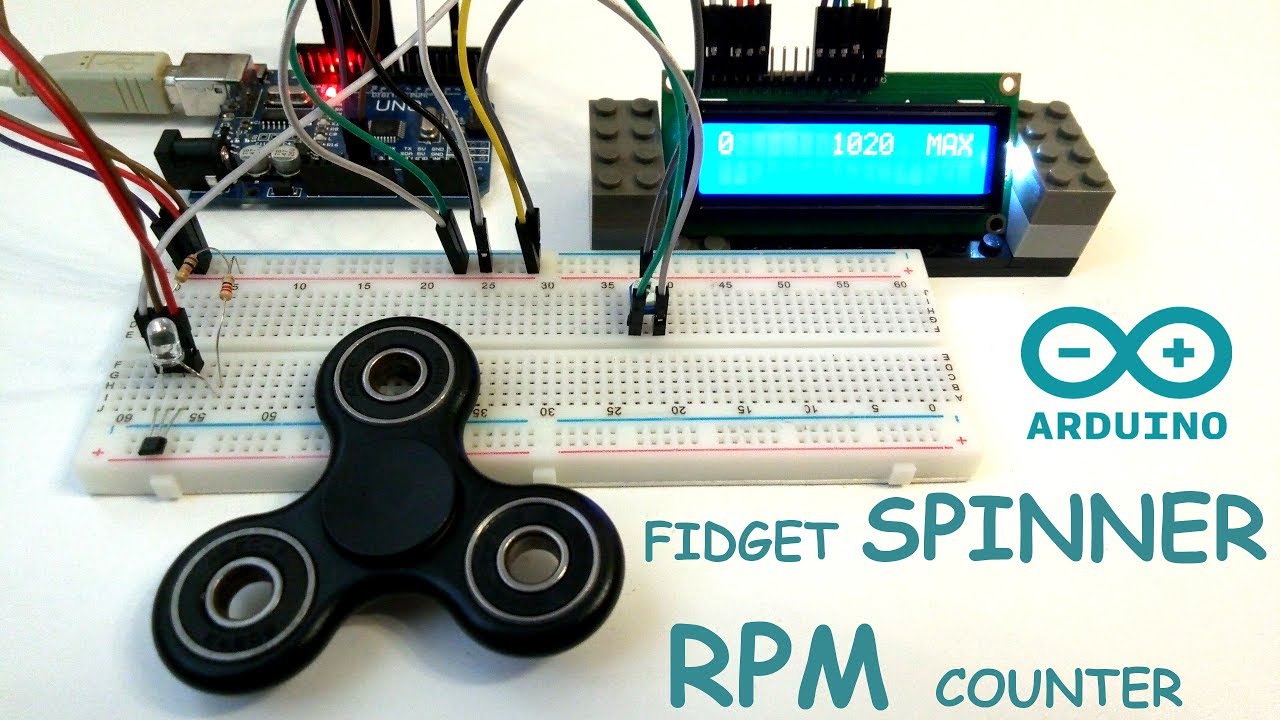
Image Result For Hall Effect Sensor Arduino 1344 Fidget Spinner Arduino Hall Effect

