Arduino Stepper Motor Speed Control Potentiometer

How To Control Stepper Motor Using Potentiometer And Arduino Arduino Stepper Motor Control Arduino Motor Control Stepper Motor Arduino

Tutorial Use A Potentiometer To Control A Stepper Motor Overview Sometimes Keeping Things Simple Is Arduino Motor Stepper Motor Arduino Stepper Motor Control

How To Control Speed Of Stepper Motor By Potentiometer Arduino A4988 Tutorial Electric Diy Lab Stepper Motor Arduino Arduino Stepper

Arduino Control A Dc Or Stepper Motor From A Potentiometer Hobby Components Blog Arduino Stepper Motor Arduino Motor

Control The Direction And Speed Of Stepper Motor Using Arduino Tinkbox Stepper Motor Arduino Arduino Stepper Motor Control

Control A Nema 17 Stepper Motor With Arduino And Drv8825 Stepper Motor Arduino Stepper Stepper Motor Arduino
A 12 volt dc.
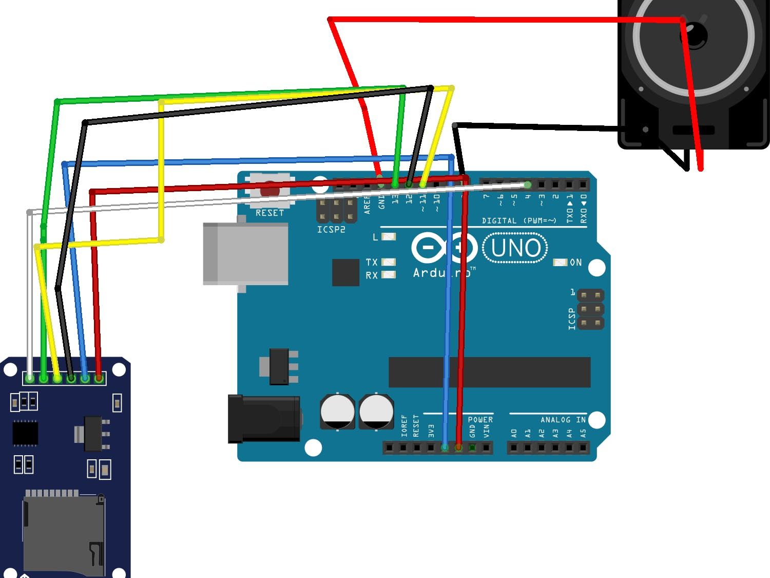
Arduino stepper motor speed control potentiometer. Some m f jumper wires. Arduino bipolar stepper motor control code. To energise the four coils of the stepper motor we are using the digital pins 8 9 10 and 11. Circuit diagram for rotating stepper motor using potentiometer.
The push button which is connected to arduino pin 4 is used to change the rotation direction of the stepper motor. In this post we will learn about stepper motor control with potentiometer and arduino. Dc motor is the most used motor in robotics and electronics projects for controlling the speed of dc motor we have various methods but in this project we are controlling dc motor speed using pwm in this project we will be able to control the speed of dc motor with potentiometer and we can adjust the speed by rotating the knob of potentiometer. Since a potentiometer can change value even when we are not touching it we are moving the motor only if the potentiometer value has changed 6 or 6 from the previous.
A lot of m m jumper wires. We have used the 28byj 48 stepper motor and the uln2003 driver module. A stepper motor driver be it l298n af motor shield a4988 or drv8825 the latter two are recommended since the current output of these drivers can be adjusted. Here it is possible to run the motor an infinite amount either way.
The pot controls how fast the motor runs and in which direction. The circuit diagram for the controlling stepper motor using potentiometer and arduino is shown above. A stepper motor a potentiometer and an arduino the hw ingredients for this blog post. And the target position target pos and use this to control the motor.
We will be using the accelstepper library to control the speed and acceleration of the stepper motor we want the motor to move in relation to the rotation of the potentiometer. An arduino board arduino uno being a beginner friendly board is recommended.

Stepper Motor Control Speed Control This Program Drives A Unipolar Or Bipolar Stepper Motor The Arduino Stepper Arduino Stepper Motor Control Arduino

Arduino Stepper Code Basics Arduino Stepper Arduino Stepper Motor Arduino

How To Control Speed Of Stepper Motor By Potentiometer Arduino A4988 Tutorial Youtube Stepper Motor Diy Electrical Electronics Projects Diy

Controlling Nema 17 Stepper Motor With Arduino And A4988 Stepper Driver Module Stepper Motor Stepper Motor Arduino Arduino

How To Interface Stepper Motor With Arduino And Stepper Motor Driver Stepper Motor Arduino Arduino Stepper

Most Used Motor Drives And Its Uses Arduino Arduino Projects Hobby Electronics

Using Sn754410 H Bridge Motor Control Driver And Ir Sensor To Control Dc Motor In Arduino Project Arduinoproject Motors Irsens Arduino Sensor Circuit Design

Servo Motor Control Via Bluetooth With Potentiometer Arduino Projects Arduino Bluetooth

Arduino Control A Dc Or Stepper Motor From A Potentiometer Hobby Components Blog Motores Carpinteria

Arduino Brushless Dc Motor Speed Control Circuit Arduino Arduino Motor Electronic Speed Control

Stepper Motor Nema 17 Controlled With Stm32 Microcontroller Arduino Stepper Motor Arduino Robot

How To Build A Simple Pwm Dc Motor Speed Controller Using Atmega8 Microcontroller Mosfet And Pot Youtube Motor Speed Microcontrollers Electronic Schematics

This Post Shows How To Control A Dc Motor Speed And Direction Using Arduino Joystick And L293d Driver The Joystick Ps2 Joystick Arduino Joystick Motor Speed

Circuit Hardware For Control Nema 17 Stepper Motor With Arduino And Drv8825 Arduino Stepper Motor Control Stepper Motor Arduino

Controlling A Servo Motor With A Potentiometer Arduino Arduino Arduino Projects Servo Arduino

Arduino Dc Motor Speed And Direction Control With L293d Motor Driver The Speed Is Controlled Using A Potentiometer Connect Arduino Motor Speed Circuit Diagram

Control A Nema 17 Stepper Motor With Arduino And Drv8825 Arduino Stepper Motor Control Stepper Motor Arduino

Arduino Using A A4988 Board To Control A Stepper Motor Youtube In 2020 Arduino Arduino Cnc Stepper Motor
Https Encrypted Tbn0 Gstatic Com Images Q Tbn 3aand9gcqasx5fujxjdgnyu0agxq2jih0hud1kx6sl3vlcxvw Usqp Cau

L298 Motor Control Module Arduino Potentiometers Computer Power Supplies Arduino Stepper Motor

Arduino How To Control A Stepper Motor With Potentiometer Nel 2020 Progetti Arduino Arduino

Arduino Servo Motor Control Using Joystick Circuit Projects Arduino Arduino Projects

Arduino How To Control A Stepper Motor With Potentiometer Arduino Stepper Motor Control Arduino Stepper Arduino

Dc Motor Control Arduino Tecnologia Electronica

Controlling Dc Motors With The L298n H Bridge And Arduino Arduino Arduino Motor Control Arduino Motor
Pin En Arduino

How To Use A Speed Sensor With Arduino Brainy Bits Raspberry Pi Arduino And Others

How Servo Motors Work How To Control Servos Using Arduino Mechatronics Arduino Quadcopter Diy

Pin On Raspberry Pi

28byj 48 Stepper Motor Control System Based On Arduino With Uln2003 Chip Arduino Stepper Motor Innovation Design

You Don T Have To Spend A Lot Of Money To Control Motors With An Arduino Or Compatible Board After Some Hunting Arduino Stepper Stepper Motor Arduino Projects

Arduino Nema Stepper Control With Joystick And Limit Switches Brainy Bits Arduino Stepper Motor Arduino Stepper Motor Control

Uctronics Stepless Dc Motor Controller Dc 10 50v 60a Motor Speed Controller With Adjustable Potentiometer Forward Brake Reverse Switch And Led Indicator For Motor Speed Led Indicator Arduino Motor Control

How Servo Motors Work How To Control Servos Using Arduino Mechatronics Arduino Quadcopter Diy

High Power Control Arduino Tip120 Transistor Arduino Projekte Arduino Elektronik

Pwm With Forward And Reverse Finally Dc Motor Speed Controller Simple Circuit Electronics Circuit Electronic Circuit Design Electronic Circuit Projects

L298n Dc Stepper Motor Driver Shield Modulo De Controlador De Doble Puente H Para Arduino Electronics Apple Electronic Accessories Diy Kits

Pwm Motor Speed Controller Circuit Using Ic556 With Switches Motor Speed Circuit Diagram Circuit

Nodemcu Esp8266 Lua Module To Drive The Cheap Stepper Motor 28byj 48 Uln2003 Combo Which Needs 3 Lines Of Code To Get Started

Arduino Easy Driver Stepper Motor Tutorial Arduino Motor Arduino Stepper Arduino Stepper Motor Control

Circuit Diagram For Iot Based Smart Irrigation System Using Soil Moisture Sensor And Esp8266 Nodemcu Automatic Irrigation System Irrigation System Iot Projects

71 Arduino Stepper Motor Passo Passo Azionato Da Due Pulsanti Progetti Arduino Progetti Arduino Arduino Elettronica

